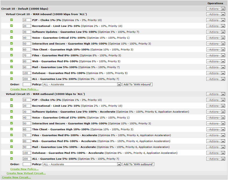
Policy Tree
All network behavior that you want to modify by using the Exinda appliance is specified by policies in the optimizer. This includes traffic shaping, prioritization, acceleration, and packet marking. These policies are arranged hierarchically in a tree so that you can assign different policy rules to different types of traffic on your network. The hierarchy consists of circuits, virtual circuits, and policies.
Role of circuits, virtual circuits, and policies
The policy tree is arranged as a three-level hierarchy. The top level of the hierarchy consists of circuits that partition the traffic by bridge. The second level of the hierarchy consists of virtual circuits that logically partitions each circuit. The third level of the hierarchy consists of policies that define which actions to take on the traffic.
Circuits relate to physical connections to the Exinda appliance. For appliances with more than one bridge configured, you can create a separate circuit for each bridge or you can treat all bridges as one combined circuit. Typically, one circuit would be created for each physical link.
A circuit can contain one or more virtual circuits for the purpose of partitioning the traffic that falls in that circuit. The virtual circuit defines what traffic will be processed in this partition and how much bandwidth it is allowed. Each virtual circuit will have it's own set of policy rules. The following are common use cases for virtual circuits.
- A circuit needs to be partitioned into traffic destined for a remote office versus traffic destined for the Internet.
- A circuit needs to be partitioned into traffic destined for particular branch offices.
- You are a service provider and your circuit needs to be partitioned into traffic destined for each of your customers.
- You have an asymmetric circuit and you want to control absolute bandwidth limits (e.g. To guarantee 100 kbps for VoIP traffic inbound and outbound).
- You want to control and monitor different subnets in your network (e.g. One virtual circuit to control and monitor your wifi network, and another to control and monitor your servers, and another to control and monitor your back-office computers.)
- You want to enforce fair sharing amongst the network hosts in the virtual circuit.
- You want a certain number of hosts or connections to get preferential treatment such as having access to a high-bandwidth virtual circuit.
Each virtual circuit contains a set of policies that define what actions to perform on each type of traffic. Policies can shape the traffic by throttling traffic, blocking traffic, or prioritizing important traffic higher than unimportant traffic. Policies can also accelerate the traffic by using acceleration techniques or caching techniques. Policies can also merely monitor the traffic. The following are common uses for policies.
- Policies to throttle or block non-critical traffic, such as P2P traffic.
- Policies to protect business-critical traffic, such as Mail or Database traffic.
- Policies to protect and prioritize business-critical latency sensitive traffic, such as voice traffic.
- Policies to throttle a particular user or host, such as throttling John's access to streaming videos.
- Policies to protect a particular subnet, such as a server or set of servers.
Circuits, virtual circuits, and policies can be managed by selecting various options from the drop-down to the right of the respective item.
To learn more about circuits, virtual circuits, or policies, see Circuits, Virtual Circuits, and Policies.
How traffic is evaluated against the policy tree
Traffic is evaluated against the hierarchical policy tree in a top-down manner. That is, the traffic is evaluated against the circuits in top-down order to determine which circuit will be handling the traffic. Once the appropriate circuit is determined, the traffic is evaluated against that circuit's virtual circuits in top-down order to determine which virtual circuit will be handling the traffic. Once the appropriate virtual circuit is determined, the traffic is evaluated against that virtual circuit's policies in top-down order to determine which policy will be handling the traffic. Any given packet will only be handled by one circuit, one virtual circuit, and one policy.

|
Note
Special care is needed when creating virtual circuits based on limiting the number of active connections, or limiting the number of active hosts, or providing fair sharing between the active hosts. When a connection or host limit is reached, it will not longer match any incoming traffic. Therefore, connections or hosts that arrive later will be evaluated against the remaining virtual circuits in the circuit. You should ensure that the overflow connections or overflow hosts are handled according to your business needs by creating a virtual circuit immediately after the virtual circuit based on limits that deals with that traffic appropriately.
Later, once some of the active connections or active hosts in the virtual circuit terminate, the virtual circuit will be used to match new traffic again.
|
|
Consider the scenario where the first circuit is defined to match bridge br10, the first virtual circuit within that circuit is defined to match the subnet for a particular branch site Springfield, and the first policy within that virtual circuit is defined to match P2P traffic.
Traffic arrives. If the traffic arrives on br10, then it is evaluated against that circuit's first virtual circuit. If the traffic matches against the Springfield subnet, then it is evaluated against its first policy. If the traffic matches P2P, then the action within the P2P policy is taken.
In each case, if the traffic did not match a given circuit, then the traffic would be evaluated against the next circuit. If the traffic did not match a given virtual circuit in the circuit that was matched, then the traffic would be evaluated against the next virtual circuit. If the traffic did not match a given policy in the virtual circuit that was matched, then the traffic would be evaluated against the next policy.
|
Order matters
Given the top-down evaluation order, if you have multiple virtual circuits that could match the same traffic although one is more specific than the other, the more specific virtual circuit needs to be ordered higher in the circuit's list of virtual circuits as compared to the more general virtual circuit. Otherwise the traffic would be caught by the general virtual circuit and would never reach the more specific virtual circuit. This is true for policies as well. That is, more specific policies need to be ordered higher in the virtual circuit's set of policies as compared to more general virtual circuits.
|
Consider the scenario where you throttle streaming traffic to 5% of your network and yet John is getting most of that 5%. You could create a policy that throttles John's streaming to 2%. John's streaming policy needs to be ordered higher in the policy tree than the general streaming policy or else his traffic will be handled by the general policy and his traffic will never be evaluated against the policy that was created specifically for his traffic.
|
When traffic is not caught by the policy tree
There are Auto-Catch All circuits, Auto-Catch All virtual circuits and Auto-Catch All policies for any traffic that does not get caught by your configured circuits, virtual circuits, and policies. Auto-Catch All do not have any policies applied to it, but they are monitored and will be shown on the virtual circuit graph.
Consider a configuration where you have two bridges on the appliance. If you define a circuit for the first bridge but not the second, then any traffic that comes in on the second bridge will fall into the Auto Catch-All circuit and will not have any of your policies applied to it.
Similarly consider a configuration where you have a circuit that will capture traffic for your entire office. You define multiple virtual circuits for each subnet that you are interested in, but your virtual circuits do not cover your entire office. For example, you have virtual circuits for your WiFi network, your servers, your staff desktop network, but perhaps you forgot your printers. The system will automatically define a virtual circuit for the remaining traffic called Auto Catch-all. Any traffic that falls into a circuit, but not into any of the circuit's virtual circuits, will fall into the Auto Catch-all virtual circuit and will not have any of your policies applied to it.
Finally consider a configuration where you have a virtual circuit that captures all the traffic for a particular virtual circuit, such as your WiFi network. You define policies for each type of traffic that you want to control or protect or accelerate, but do not include all the traffic on your WiFi network. For example, you have policies for P2P, streaming, and web, but you do not have policies for software updates. The system will automatically define a policy for the remaining traffic called Auto Catch-all. Any traffic that falls into a virtual circuit, but not into any of policies, will fall into the Auto Catch-all policy and will not have any of your policies applied to it.
Consider the opposite scenario where you have more than one circuit that could capture the same traffic. For example, you have two circuits that could both capture br10 traffic. The traffic will be evaluated against the virtual circuits and policies within the first circuit. If the traffic does not match any virtual circuits and policies in the first circuit, then it will attempt to match the traffic to the virtual circuits and policies in the second circuit. If the traffic does not match any of the virtual circuits and policies in any of the matching circuits, then the traffic will fall into the Auto Catch-All virtual circuit and Auto Catch-All policy in the last matching circuit and will not have any of your policies applied to it.

|
Best Practice:
It is a best practice to explicitly create your own "catch-all" policy so that you can apply the appropriate control and prioritization.
|
If traffic is not caught by a circuit or by a virtual circuit or by a policy, it will show up in the real-time monitor as an Auto Catch-all circuit and an Auto Catch-all virtual circuit and an Auto Catch-all policy. The Auto Catch-all circuits and virtual circuits will also be shown on the Virtual Circuit monitor report.
Enabling policies
Policies that are enabled are shown with a green checkmark in the policy tree. Policies that are disabled are shown with a red x. You can toggle the enable state by clicking the checkmark or x.
|
|
Note
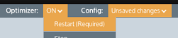
Whenever the Optimizer is modified, it must be restarted before the changes will take effect on your traffic. Restart the Optimizer, by selecting the Optimizer menu in the status bar at the top of the screen.
|
Re-use policies from the library
Policy definitions are created and saved to a policy library. This allows the same policy definition to be used in more than one virtual circuit. Therefore, if you edit a policy in one virtual circuit, the definition will be modified for all virtual circuits. To modify a policy for a specific virtual circuit, it is recommended that you clone the policy then modify the details. Note that when policies are removed from a virtual circuit, they will not be deleted from the policy library.
 To add a policy
If you want to add a policy that already exists in the policy library
- Select the desired policy using the drop-down list at the bottom of a virtual circuit's policy list in the Optimizer.
- Specify the rank order number so that it will be inserted in the desired location in the policy tree.
- Press the Add to 'name of virtual circuit' button.
If you want to create a brand new policy
- Click on the Create New Policy link at the bottom of the desired virtual circuit's policy list and fill out the policy details.
- The system will insert the policy to the bottom of the policy list for the given virtual circuit. Reorder the policy if needed. See To reorder policies section below.
To reorder policies
For each policy that you would like moved, edit the ranking number to the order you would like, then select Reorder from the Actions menu on the right-hand-side. For example, if there are already policies with ranking order 10, 20, and 30, and you want to swap the order of the policies with ranking order 20 and 30, then either change the ranking order of 30 to be between 10 and 20, say 15, or change the ranking order of 20 to be after 30, say 35. In either case, select Reorder from the Actions menu on the right-hand-side of the policy that changed its ranking number to submit this change.
To reorder virtual circuits
For each virtual circuit that you would like moved, edit the virtual circuit by selecting Edit from the Actions menu on the right-hand-side. Then modify the rank, which is the editable text field as part of the Virtual Circuit Number. For example, if there are already virtual circuits with ranking order 10, 20, and 30, and you want to swap the order of the virtual circuits with ranking order 20 and 30, then either change the ranking order of 30 to be between 10 and 20, say 15, or change the ranking order of 20 to be after 30, say 35. In either case, select Reorder from the Actions menu on the right-hand-side of the virtual circuit that changed its ranking number to submit this change.
To delete a policy from the system
To delete a policy from the system, it must be deleted from the policy library (Configuration > Traffic Policies > Optimizer > Policies).