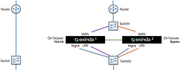
Given a topology without router redundancy (shown in the image on the left), you can configure the Exinda solution in cluster mode (shown in the image on the right) to achieve high availability of the Exinda appliances or to support a greater number accelerated connections. The Exinda appliances will act as a single appliance, yet will provide high availability.
In this topology, both Exinda appliances are connected to the router via a WAN switch. The two appliances are directly connected to each other and forwards its traffic to the other appliance. Note that the traffic that is received from the other Exinda appliance will not be forwarded onto the LAN. Both appliances report on the data in the same way.
The Exinda appliances also automatically synchronize configuration settings between the two appliances.
|
|
Note To configure for high availability such that there is an active path and a standby path: Your WAN switch (Switch 1) and LAN switch (Switch 2) must support the Spanning Tree Protocol (STP). Configure the STP in Switch 2, so that port 1 (connected to Exinda 1) has higher priority then port 2 (connected to Exinda 2). If the link at switch 2/port 1 goes down (e.g. Exinda 1 loses power), then the switch will enable switch 2/port 2. Exinda1 should configure NoLink as the bridge failover option, Exinda 2 should configure Bypass.
|
|---|
All platforms support this topology.
|
|
Note Switch2/port1 should have the highest STP priority. |
|---|
|
|
|