A transaction is defined as a client request followed by a server reply, including both TCP and UDP flows. With each read and write transaction between a client and a server, the following values are measured and used to calculate how long the transaction takes to complete:
Round Trip Time (RTT) is the measure of how long it takes for a very small packet to travel across the network and for an acknowledgment of that packet to be received. Consider the typical topology where an Exinda appliance is positioned between the client and the server. As each packet is intercepted by the Exinda appliance, it is time stamped with a highly accurate nanosecond resolution clock source. Since the Exinda intercepts the packet after the client sends the packet, the start time is not known and so the RTT is determined by summing the round trip time from the Exinda appliance to the server and back (Server RTT) and the round trip time from the Exinda appliance to the client and back (Client RTT). As more packets are sent from the client through the Exinda appliance to the server and back, the RTT estimate is updated by averaging new information.
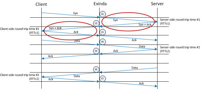
The following diagram illustrates how the round trip time is calculated:
Server RTT:
RTTs1 = t2 - t1
RTTs2 = t5 - t4
Client RTT:
RTTc1 = t3 - t2
RTTc2 = t7 - t6
Average Server RTT = (RTTs1 + RTTs2)/2
Average Client RTT = (RTTc1 + RTTc2)/2
Average Total RTT = avRTTs + avRTTc
When a client computer requests information from the server, the request and response are tracked to determine how long it takes for the client to send the request, and the server to send the requested data back to the client. The diagram below shows the flow of information between the client, the Exinda appliance, and the server, and identifies the points in the transaction where time stamps are acquired.
![]()
When the end of the request passes through the Exinda, the time stamp is noted (t2).
t2 – t1 = The amount of time it takes the client request to pass through the Exinda appliance.
When the end of the last response passes through the Exinda, the time stamp is noted (t4).
t4 – t3 = The amount of time it takes the data requested by the client to pass through the Exinda appliance.
The total transaction time for a Read transaction is calculated as Transaction time = N1 + S + N2 where:
N1 = ½ RTTclient + (t2 – t1) + ½ RTTserver
S = (t3 – t2) – RTTserver
N2 = ½ RTTserver + (t4 – t3) + ½ RTTclient
When a client computer sends information to be written to the server, the request and response are tracked to determine how long it takes for the client to send the data to the server, and the server to send acknowledgment of receiving the data back to the client. The diagram below shows the flow of information between the client, the Exinda appliance, and the server, and identifies the points in the transaction where time stamps are acquired.
![]()
When the end of the last data packet passes through the Exinda, the time stamp is noted (t2).
t2 – t1 = The amount of time it takes the client to send data through the Exinda appliance.
When the end of the response passes through the Exinda, the time stamp is noted (t4).
t4 – t3 = The amount of time it takes the server response to pass through the Exinda appliance.
The total transaction time for a Write transaction is calculated as Transaction time = N1 + S + N2 where:
N1 = ½ RTTclient + (t2 – t1) + ½ RTTserver
S = (t3 – t2) – RTTserver
N2 = ½ RTTserver + (t4 – t3) + ½ RTTclient
To create accurate comparisons of the network delay experienced by a transaction, the appliance must analyze packets of the same size (normalized). All other factors being equal, the transaction delays should increase with the amount of data transferred or the transaction size.
To make the APS score independent of transaction size, the transaction delay metrics are normalized using a constant of 1024 bytes. The normalized network delay is calculated as follows:
Normalized Network Delay = Total Network delay * 1024 / transaction bytes
|
|
Note Due to the nature of normalization, protocols that naturally use very small sized packets (like RDP and Citrix) will produce APM values higher than the real ones given such that the results are being multiplied by 1024. The number of bytes used to normalize the calculation of the network delay during a transaction can be configured through the CLI, as well as disabling normalization altogether. |
|---|
Packet loss occurs when one or more packets within a transmission are successfully sent, but fail to arrive at the destination. Packet loss can be caused by a variety of factors including network congestion, faulty network components such as hardware or drivers, or corrupted packets within the transmission. If the transmission experiences packet loss, it may cause the following:
To recover from packet loss, data must be retransmitted to the destination to complete requests successfully. The amount of data retransmitted per flow is used to calculate the Network Efficiency metric.
Efficiency = 100% * (transferred - retransmitted) / transferred
and
Network Loss = 100 - Efficiency
|
|
Note Network loss, not efficiency, is used when calculating APS. |
|---|
|
|
|